
the black one or ?

 Busted Cambelt


the black one or ?
Dirty idler valve
The first one is a na setup but a pleum is available to run boost.
Dirty idler valve
Very interesting discussion and info, thanks.
One short note if we come back to Q4 vs Kappa turbo - kappa manifold has shorter runners as compared to OEM Q4 inlet manifold. So OEM Q4 set should be better for higher torque at low RPM as compared to kappa one...
Busted Cambelt
Correct and vs the kappa would give more in high romOriginally Posted by mindus

Blueprinted

So, the oem Q4 set up {compared to Delta Integrale and Kappa set up} is better for higher torque at low rpm. And worse for the high rpm.
What about having
a} short run at the inlet manifold,
b} 4 throttle bodies
and
c} a small 'plenum' just as a 'connecting tube - box' to the turbine?
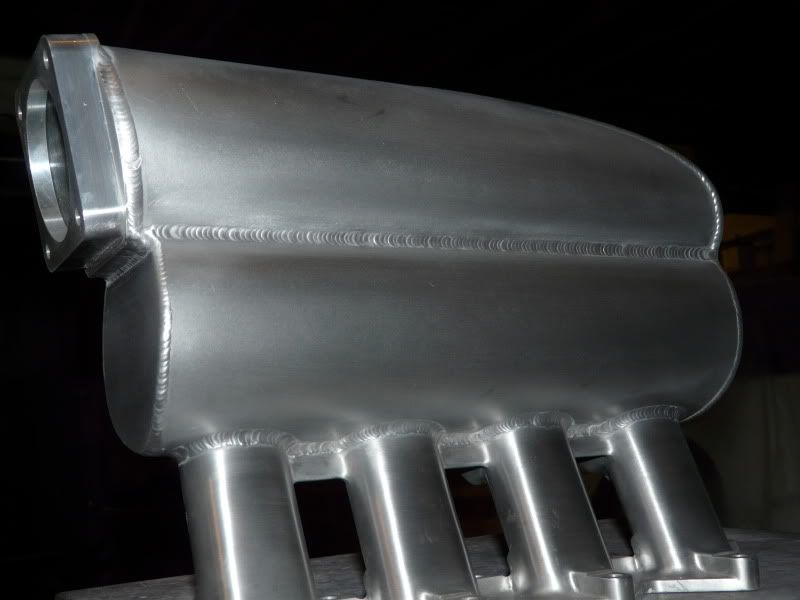
Something like the very first picture I've posted {from B&M engineering}?
Does anyone has a thought - opinion about?
Nick
Dirty idler valve
1NR0; It is really a beautiful piece of work your inlet manifold, and very unconventional. Please tell us more what your idea is with this design. I suppose you have made some calculations, what do you expect from it?
I do not fully understand the layout, is it meant to be one long fat tube folded 180 degrees on the middle?
When you have put some much effort in it, why do the intake runners hav so sharp edges at the plenum connection? Or is it suppose to not matter? I realise that the accoustic tuning will give a more disticnt resonance frequency (if that is desireable) but the flow capacity will be decreased. Or?
Is it a 90 mm TB?
Dirty idler valve
What you describe there Nick is a inlet manifold designed for a mid to high rpm range such as competition cars spend most of their time at.
A small plenum will achieve nothing at any rpm level, if anything it'll be something the engine exceeds in it's demand, it'll not keep up. A big plenum will do no harm.
The best for what sounds like your target of low rpm response would be the Kappa with it's full length runners but a bigger plenum welded on, whilst the plenum is cut off you'd have the access to the runners to port them and ease them out to as big a taper in their length you can manage with the thickness of the alloy. This starts the speeding up of the intake charge (velocity) along the full length of the inlet port which the runner is part of remember. I personally wouldn't bother with trying to improve the low rpm response on it's own, target a higher rpm level and make sure the induction system has nothing to restrict it's passage to the engine, big spaces don't cause restiction, reduced cross section does that. A given square inch of area will only pass so much air, turning up the boost isn't the way to do it, there is plenty of air available, you just need to get it to the engine without restriction. boost doesn't hardly make any difference to the volume of air the engine can consume, the air mass however is a different matter all together.
Nik
Dirty idler valve
I've speced the dimensions to be something that comes on tune at about 8500 rpm which will allow me to pull past that up to 9500 rpm which is my target redline. I'm limited by turbo size to a power level in the 600 + bhp region, the turbo has been pushed to over 700bhp by some people which maybe I'll get near (one day when I get this bloody engine finished!). The inlet manifold you see is well capable of these targets and beyond if a bigger flowing turbo is used in the future.
The runner entrance in the posted picture is mid way through fabrication, there is a slight increase in radius since working it some more. The demand of the engine is less than what the runner will flow so no gain by making it more gentle in it's entrance, if anything the clear definition of the entrance improves the strength of the reflective pulse when it drops into the range. A big radius would dampen this pulse. A piccy of before and after a bit more work http://s3.photobucket.com/albums/y85...t=9098c523.pbw there's been a bit more since then but not a hacking of a big radi onto the entrance.
The plenum is two plenums with a dividing partition which equalises the air as it passes into the lower plenum, the engine can then call upon a consistant supply of air without worrying that one cylinder is getting more air than another due to a bias or area of inconsistant turbulance. Bit like a Swedish plenum
Just a little 80mm TB
Nik
Blueprinted
Thank you very much for all the notes Nik. I'll keep them in mind.
Nick
Dirty idler valve
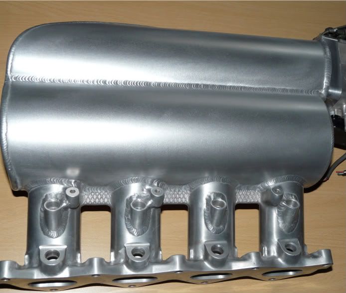
Though maybe it'd be of interest to see the manifold now it more or less finished. still a throttle cable mount to make and weld on and a couple of little bits but basically it'll look like this. I'm happy.
Vice President: Newsdesk
Site Admin
Very impressive...there's been some skilled time spent on that
wrinx
My Q4 in the Garage
www.alfaromeo155.co.uk ............................ □□□-V-□□□ .................................. www.ilmostro.co.uk
Dirty idler valve
Thanks. A whole heap of my hours doing the fabrication and some serious skill by the welder to do approx 12 ft of weld to that standard and the local engineer who did some funky machining at various stages. One manifold down, one to go.
Nik
Vice President: Newsdesk
Site Admin
Definitely a welder to stay friends with, some really excellent work there (I used to do a lot of welding, including non-ferrous)...does he do custom intercoolers?
wrinx
My Q4 in the Garage
www.alfaromeo155.co.uk ............................ □□□-V-□□□ .................................. www.ilmostro.co.uk
Dirty idler valve
He can weld pretty much anything to anything it seems, master of his trade. I've a loooonnnngggg list of things to fabricate to send down to him for final welding, one of which is my intercooler.
Running smoothly
Great work!!!
I do understand what you're aiming with 2 chamber/plenum, but how are they connected?
You will be using 2 staggered fuel rails or H2O/alcohol injection?
Dirty idler valve
Just a provision for flow that is the equal plus a bit to the throttle body which is the smallest part of the inlet system
It's going to be twin fuel rails and E85 through them both.
Busted Cambelt
Woow, it looks superb.. Mass production or at least just one for me...
What ecu are you going to use with the twin injectors.. I am just doing twin injectors on my Kappa inlet manifold.
Chip tuning
Kepsus - can you please update me on the benefits of dual injectors with this sort of setup? I used to use them on a race-car that used twin DCOE throttle bodies and the 2nd injector set was WAY outside of the inlet manifold and squirted across an air space - so i used the 1st injector set to inject into the normal place when revs and intake velocity were low.
But how will they help on a Q4?
One thing I would say is that I have upgraded my injectors from the 384cc standard ones to the DEKA IV 630cc ones... but .. if you are going to use E85 .. and... you are planning on making north of 300hp then the 630cc injectors and only just big enough!
Dirty idler valve
Thanks. Mass production isn't likley, it was very labour intensive to make and very costly in materials and subcontracted labour. I'd consider a commission but people for that expense would be few and far between.
I'm going to run the eight injectors in batch fire using a motec m4 initially but for the future would like an ecu that will run them sequentially. just keeping it simple for now.
Nik
Busted Cambelt
Thanks.
Jimmie, i am just making them now, but my point was use the original injectors as primay, and then my 770cc injectors as secondary. I am using Omex 710.
The reaso is that i would like to have the best from two world, i have tryed to only use the 770 it works fine, but in the low rpm and Idle thay do not work well, even that i am using full sequentiall
 Posting Permissions

 Reply With Quote


")
Bookmarks